REQUEST A QUOTE
Cadillac® Ultrasonic Meter
The Cadillac® Ultrasonic Flow Meters are rate and totalizing meters which are capable of measuring liquids, of all types, non-intrusively.
The Cadillac® Ultrasonic Flow Meters are rate and totalizing meters which are capable of measuring liquids, of all types, non-intrusively. Due to its universal (one size fits all) design and ease of installation, it is particularly suitable for Hot and Chilled water measurements.
Integrating Digital Processing (DSP) with advanced correlation detection methods, the flow meter features exceptional performance and flexibility. Combining ease of installation (non-intrusive pipe clamp-on), high accuracy, no moving parts, reliability, low maintenance, rangeability and no pressure drop, Cadillac® Ultrasonic flow meters have become the fastest growing liquid flow technology in the world today.
The Cadillac® Meter Energy Calculator is designed to measure energy consumed in hot water heating and chilled water cooling systems. Supplied with temperature probes, the calculator integrates the Cadillac® Ultrasonic Flow Meters to provide flexibility to meet all application needs. Modes of operation include: Heating, Cooling, Heating/Cooling and Charge/Discharge.
QUICK CONTACT
DOWNLOADABLE DOCUMENTS


Product Summary
The Cadillac® Ultrasonic Flow Meters are rate and totalizing meters which are capable of measuring liquids, of all types, non-intrusively.
APPLICATIONS AND FEATURES
The CS 50 Sliding Gate Back Pressure Regulator is used to regulate upstream pressure at a predetermined set point. The spring in the CS 50 holds the sliding gate seats in their normally closed position.
The upstream pressure is sensed beneath the diaphragm. As the upstream pressure exceeds the Set point, pressure is exerted on the diaphragm which raises the stem to modulate the disc (the movable component of the sliding gate seat set) toward the open position. As the seats open, upstream pressure will be regulated to the required set point. A decrease in pressure relaxes the spring and diaphragm to move the seats toward the closed position.
CS 50 Features
- Sliding Gate Trim — unique seat design for unsurpassed trim life and accuracy.
- Jorcote Seat Coating — ceramic composite for liquids, gases and especially steam. Very low friction with outstanding wear resistance. Steam tested to 1,000,000 cycles and still maintained Class IV leakage.
- Jorlon Diaphragm — extremely durable, virtually universally applicable up to 450°F, standard 316 SST diaphragm applicable up to 650°F. Tested without failure to over 1,000,000 full stroke cycles. Ideal for steam, gases and liquids.
- Straight-through Flow — The flow is straight through the valve seats and body. Direction of the disc travel is perpendicular to the flow, not opposed to the direction of the flow. Thus, the flow does not unbalance the seats. The CS50 can use a wider range of its stroke to give accurate control; less offset and rangeability up to 20:1.
- Quiet Operation — typically 5-10 dB less than conventional globe style regulators. The disc and plate are always in contact, which eliminates chattering.
- Straight-through flow minimizes turbulence. Multiple orifices in the plate and disc divide the flow stream into smaller flow components.
- Minimum Maintenance — The CS50 sliding gate seats require no special tools for disassembly. The seats are pre-lapped at the factory and are self-lapping while in operation ensuring a continual tight shutoff.
CS 50 Series:
- CS50: a line of self-operating back pressure regulators designed with CSSC Valve’s sliding gate seats
- CS51: The CS51 features a larger diaphragm than a standard CS50 to provide even greater sensitivity and more accurate regulation of your required set point
- CS50QC: The CS50QC features a “Quick Change” dome for simple range spring replacements. Ideal for facilities with multiple back pressure requirements as it is possible to stock one valve with several spare springs to cover a wide range of needs
- CS50H: The CS50H features a hand wheel that is mounted on the adjusting screw to allow easy set point changes
- CS50HP: The CS50HP option is an elongated spring housing that features a large spring for high pressure set points up to 450 psi (31,03 bar)
- CS50GP: The CS50GP option is used in grain processing for starch cookers and other viscous services
- CS50CR: The CS50CR option has a special spring housing for use if the valve is in cryogenic services
- CS501/502: The CS501 and CS502 meet higher capacity requirements than standard back pressure regulators
OPERATION PRINCIPLES
Cadillac® Ultrasonic Meter – Operation Principles
Two technologies are available from Cadillac® Meter which incorporates the use of ultrasonic energy to measure flow. Transit Time is based on time of flight, and Doppler measures frequency shift of the generated signal. The proper application of each technology is dependent on fluid conditions, and is covered below in Meter Selection.
Both flow technologies operate by generating ultrasonic energy via piezoelectric crystals embedded in two separate resin blocks, called transducers. The transducers are attached to the outside pipe wall using a sonic coupling compound (typically a silicon based grease) and retaining system (typically pipe straps), allowing the ultrasonic energy from the transducer to be transferred through the pipe wall and into the moving fluid. From this point on, the two technologies differ in their mode of operation and will be addressed separately.
Transit Time is used on clean (low suspended solids) non aerated fluids by measuring the difference in time (DT) it takes the pulsed ultrasonic energy to move from the upstream transducer and vice versa.
The difference in time of flight is directly proportional to the velocity of the moving liquid. Thus the higher velocity the greater the (DT) which is a conversion made by the flow meters’ digital signal processing (DSP) from the phase shift (DØ) between the up and downstream pulsed sonic signals.
Volumetric flow rate is then calculated by taking the measured velocity and multiplying it by the effective internal cross sectional area of the process piping, which must be programmed into the meter prior to transducer installation.
Doppler is used on dirty (high suspended solids) or aerated fluids by measuring the frequency shift of the ultrasound as it reflects or bounces off particles or bubbles in the flow stream.
One transducer acts as the source or frequency generator and the other as the frequency receiver. As the sound waves bounce off objects in the flow stream it causes a shift in frequency which is dependent on particle velocity.
The greater the velocity the more frequency shift experienced. Caution should be exercised when applying Doppler since this is essentially an inferred measurement and is made on the premise that the particles or aeration in the flow steam are moving at the same velocity as the liquid. In certain applications this premise cannot be made and velocities measured can actually be unrepresentative of the actual liquid flow stream (typically reading low in liquids with high solids or slurries). Please consult Central Station Steam Company® technical support for application review in these cases.
DIMENSIONS AND SPECS
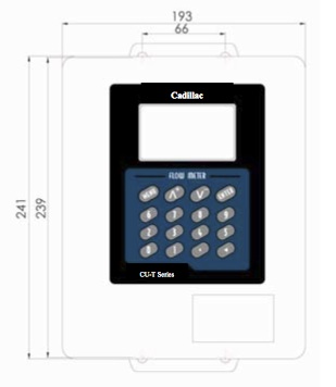
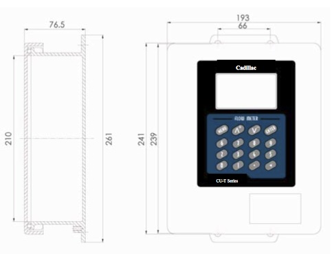
Cadillac® Ultrasonic Meter – Dimensions
Cadillac® Ultrasonic Meter dimensions are outlined below:
Cadillac® Ultrasonic Meter – General Specifications & Sizing
Cadillac® Ultrasonic Meter includes the following specifications:
Digital Correlation Transit Time
- Meter shall consist of remote electroincs and one pair of matched clamp-on transducers BNC style cable.
- Meter available with analog (4-20 mA), digital (pulse or relay) outputs, and RS485 Modbus RTU Communications.
- Four line 16 character backlit LCD providing instantaneous flow, totalized flow, velocity, and operational status.
- Meter programmed via integral keypad.
- Flow range: 0 to + 40.0 ft/s (0 to + 12.0 m/s), bi-directional flow.
- Accuracy: Typically ± 1.0% of reading at rates < 1.65 ft/s (accuracy also dependent on flow profile).
- Repeatability: 0.2% of Reading.
- Temperature Range: Transducers 4° to +250°F (- 40 to 121°C), Transmitter 4° to +130°F (- 20 to 60°C)
- Meter housing: NEMA 4X (IP65), ABS plastic (standard).
Energy Meter
- Meter shall consist of remote electroincs, one pair of matched clamp-on transducers, and pair of matched temp trans.
- Meter available with analog (4-20 mA), digital (pulse or relay) outputs, and RS485 Modbus RTU Communications.
- Four line 16 character backlit LCD providing instantaneous Energy, totalized Energy, velocity, and operational status.
- Meter programmed via integral keypad.
- Flow range: 0 to + 40.0 ft/s (0 to + 12.0 m/s), bi-directional flow.
- Accuracy: Typically ± 2.0% of reading at rates < 1.65 ft/s (accuracy also dependent on flow profile).
- Repeatability: 0.2% of Reading.
- Temperature Range: Transducers 4° to +250°F (- 40 to 121°C), Transmitter 4° to +130°F (- 20 to 60°C)
- Meter housing: NEMA 4X (IP65), ABS plastic (standard).
INSTALLATION
Cadillac® Ultrasonic Meter – Installation
Cadillac® Ultrasonic Meter installation is critical to proper operation and flow measurement for Doppler and Transit Time flow technologies. Since process piping is both the flow containment and measurement spool piece, care must be taken in location selection, mounting orientation and mounting method.
Transducer Location Selection
With regard to location selection and mounting orientation, care must be exercised to establish a point in the piping system that meets the following criteria:
- Choose a section of pipe that is always full
- Site should meet straight run requirements of at least 10 diameters upstream and 5 diameters down- stream. (Figure A)
- After a pump, control valve or double piping bend, up to 30 diameters of straight run may be required.
- On horizontal pipe, mount transducers in the 3 and/or 9 o’clock position (see mounting method). This avoids sediment that may collect on the bottom of the piping and bubbles or air pockets along the top of the piping, which can cause signal loss.
- Ensure pipe skin temperature is within transducer temperature rating (see specifications).
- If possible select a section of pipe where inside and outside are free form excessive scaling or corrosion.
If any or all off the above guidelines cannot be followed completely, it is still possible to obtain meaningful flow measurements, often with little or no loss of accuracy.
Transducer Mounting Methods
With regard to mounting methods there are four configurations, one for Doppler and three for Transit Time. Each will be discussed and illustrated separately. Doppler has one mounting method which has the traducer mounted directly across (180°) from each other on the piping.
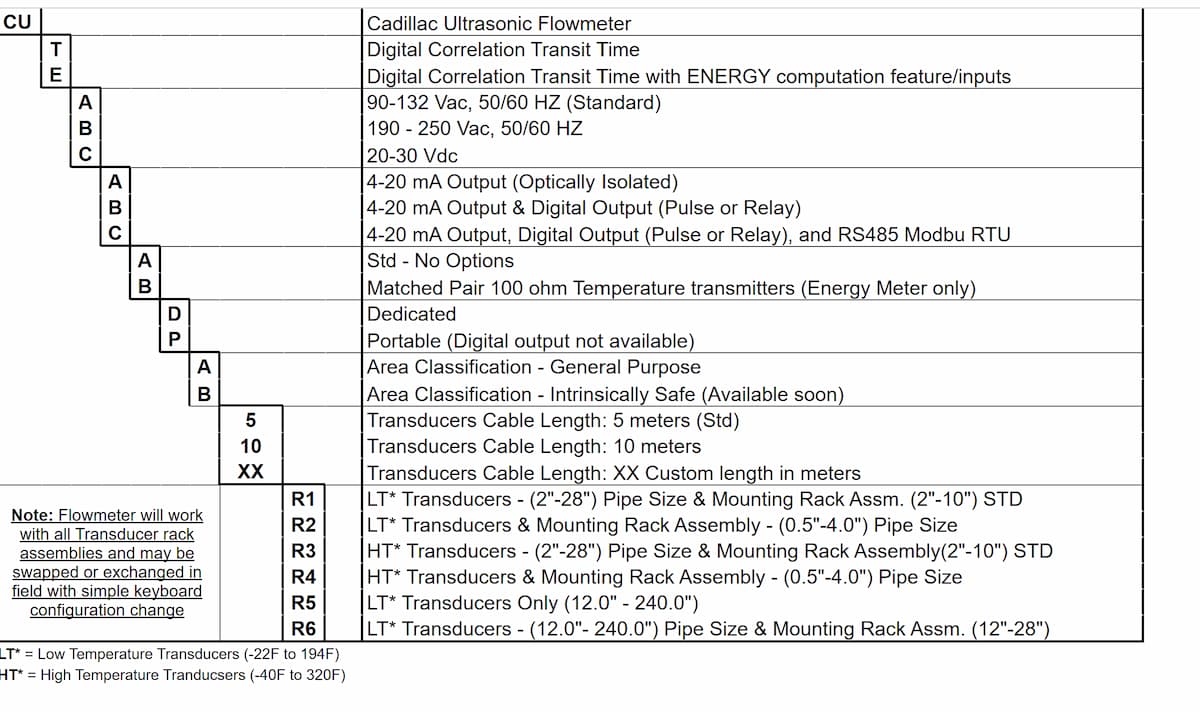
MODEL CODE
Ultrasonic & CU-E Model Mode
Related Articles

Industries That Use Condensate Meters: Where Precision Flow Measurement Matters
In the world of energy, data is power—and nowhere is that more evident than in the industries that rely on condensate meters. From massive power plants to pharmaceutical facilities, industries that use condensate meters all share one thing: the need for accurate,...
How Condensate Meters Work: A Straightforward Guide for Energy Professionals
In the energy industry, accuracy isn’t optional—it’s everything. That’s especially true when it comes to tracking steam usage and reclaiming valuable condensate. Whether you're in power generation, chemical processing, or HVAC systems, understanding how condensate...
GET A FREE QUOTE FOR YOUR NEEDS
World-class brands rely on us for their energy measurement systems
FEATURED ARTICLE

The Benefits of Sub-Metering On College Campuses
College campuses can benefit from sub-metering from a business, engineering, and management perspective— all of which are vital to an institution’s sustainability. The full weight of these benefits can vary between small and larger schools. Small colleges will benefit...
© All Rights Reserved