Now that we have established why the flow meter is the most inaccurate component of the energy measurement system, what does this accuracy/inaccuracy really mean and how does it impact the measurement? Let’s start by defining measurement. What kind of accuracy is required to make a legitimate flow measurement?
Let’s break this down into three classifications
1) Flow measurement
2) Flow indication
3) Flow switch
To define each of these we need to establish some basic accuracies as an error percentage in reading or measured value, and associate that value to each classification.
1) For the sake of a measurement, most people would agree +/- 5.0% should be the standard used. Keep in mind, the flow meter is not the only component in this calculation, and realistically, the entire measurement should not exceed +/- 5.0%. But, for the sake of keeping round numbers we will use +/- 5.0%
2) Flow indication should therefore be defined between +/- 5.0%, and in a worst case of +/- 50.0%. I realize this is a wide range, but the reason for knowing there is flow will depend on the application and the end goal of knowing that information.
3) A flow switch should be considered anything above +/- 50%. This basically gives an on/off indication to be used for some decision, which in many cases is used to start/stop pumps so they don’t run dry.
All three are valid and useful pieces of information, depending on the application and what the information is being used to achieve. However, I think we can agree that if we are going to use the information to calculate energy in order to determine usage and efficiencies, it should be a flow measurement.
As we discussed in our last post, the most accurate and flow profile independent technology is the magnetic flow meter. But, as I hinted at the end of the article, this accuracy has another critical consideration: What is the operating range the meter is expected to measure over? (Remember +/- 5.0 % or better.) This is the flow range that the application operates within, which you will see, is where any flow meter technology will be hard pressed to remain in the measurement classification.
In energy measurement applications, the operating flow range of any given flow meter has changed in regards to low-end flows or velocity. Today, the low end velocity has significantly reduced in the order of a factor of 10!
Before the advent of Variable speed drives (VFD’s) and modulating flow valves, most hot/chilled water systems worked in a pump on/off mode with parallel pumping systems to meet the demands of the application. Concerns over electricity cost and usage were minor, so the pumps would run up their pump curves, drawing as much current as required to meet the upstream pressure drop and maintain a given flow. As a first step to reduce this, pumping system VFD’s were introduced in the mid 1980’s to reduce the energy cost and provide just enough flow to meet the downstream demand. This created a new generation of products to meet the point of use requirements while reducing the energy used to meet these needs. As a result, we have a standard today where VFD’s and flow control diverting valves are employed to optimize the electricity demand required to move the water. This has, in turn, impacted the flow conditions in both new and retrofitted applications, which I have defined below in terms of low flow rate or velocity.
1) In the mid 1980’s, previous to VFD’s and automated diverting valves, the velocity range with pumps operating in an on/off mode was 1.0-15.0 feet/second
2) Today with complex pumping strategies using VFD’s and automated flow control valves, the velocity range is 0.10-15.0 ft/s, or a decrease in flow velocity by a factor of 10.
So, with a flow or velocity range defined, how exactly do the various flow technologies compare to each other and the requirement to meet the classification of “Flow Measurement”?
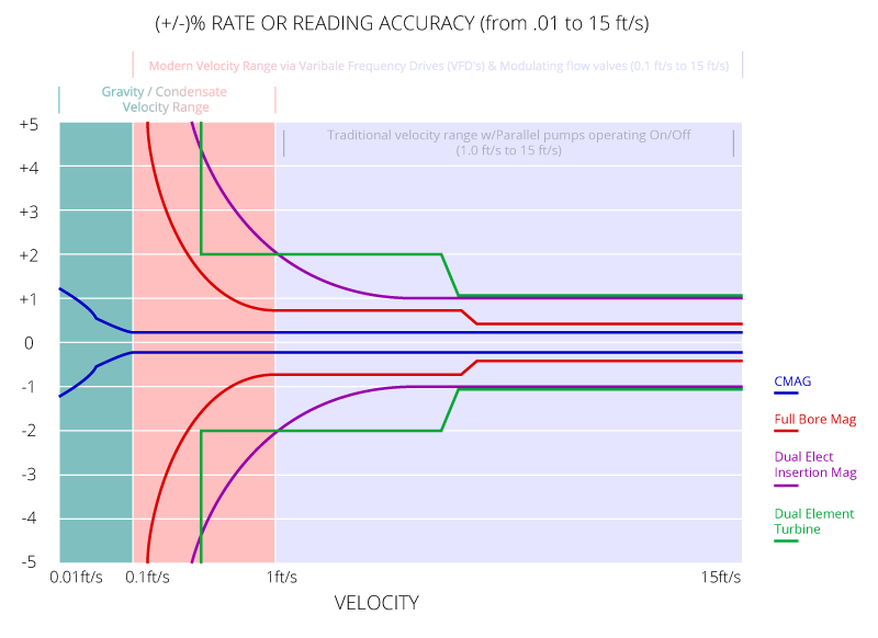
With this in mind I have taken what I consider the three most widely used technologies (dual element turbine, dual electrode insertion magmeters, and full bore magmeters) for energy measurement and compared them on a graph, which shows the percentage error maintained between +/- 5.0% of rate or reading. Hold on to your hat, because I think you will be surprised by how many of these devices do not make the cut as an energy measurement over the operating range.

So, as you can see from the graph, most of the metering technologies except the CMAG do not provide a flow measurement across the current flow or velocity operating range required today. What is more amazing is that two of the most common meters used (dual element turbine and insertion dual electrode magmeter) are poor measurements at best at the low end of the old flow standard, and not measurements at all for half of the new extended operating range!
In the case of the dual element turbine, it no longer has a working accuracy specification halfway through the new velocity range, which indicates it probably no longer functions. And, even though the dual electrode insertion magmeter still has an operating accuracy specification, its logarithmically declining accuracy makes it merely a flow indicator at the lower end.
Even the traditional full bore magmeter design becomes a flow indicator at the lower end, making a bold statement on how difficult it can be to make a flow measurement at these low flows/velocities. Only the CMAG with its unique flow tube design, which makes it immune to flow profiling and more importantly gives unprecedented turndown, is able to actually provide a flow measurement across the new operating flow range as defined for energy measurement applications.
Now that we have defined what makes an energy measurement, what does this accuracy mean exactly with regards to BTU/TON’s/Energy measurement quantitatively? And, how does that translate into efficiency calculations and dollar savings?


